Turret Automation
The next step was to automate the turret....
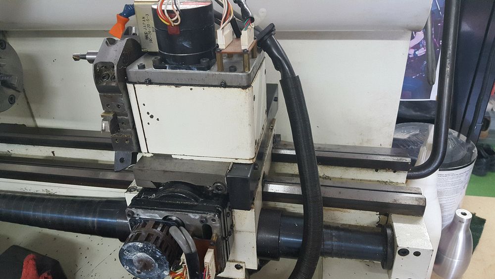
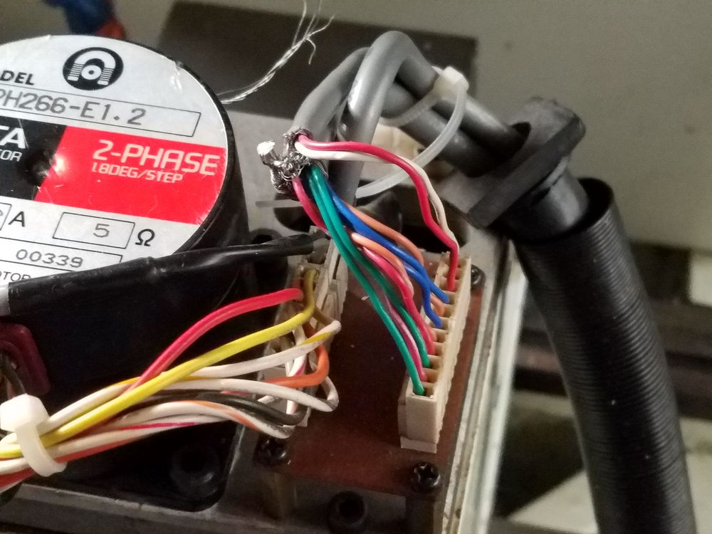
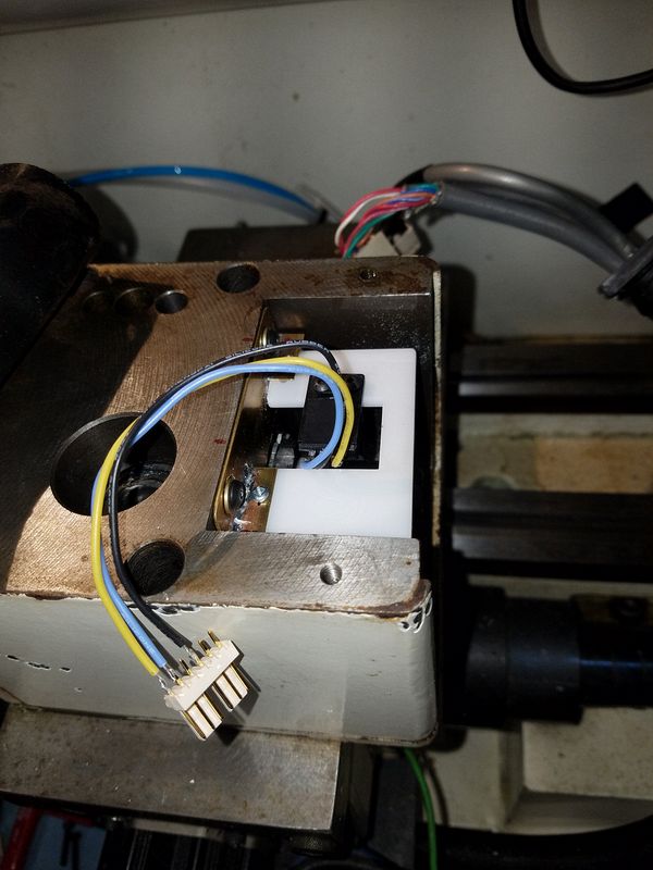
With the cover removed the turret stepper motor, lock pin solenoid and connector header are all visible.
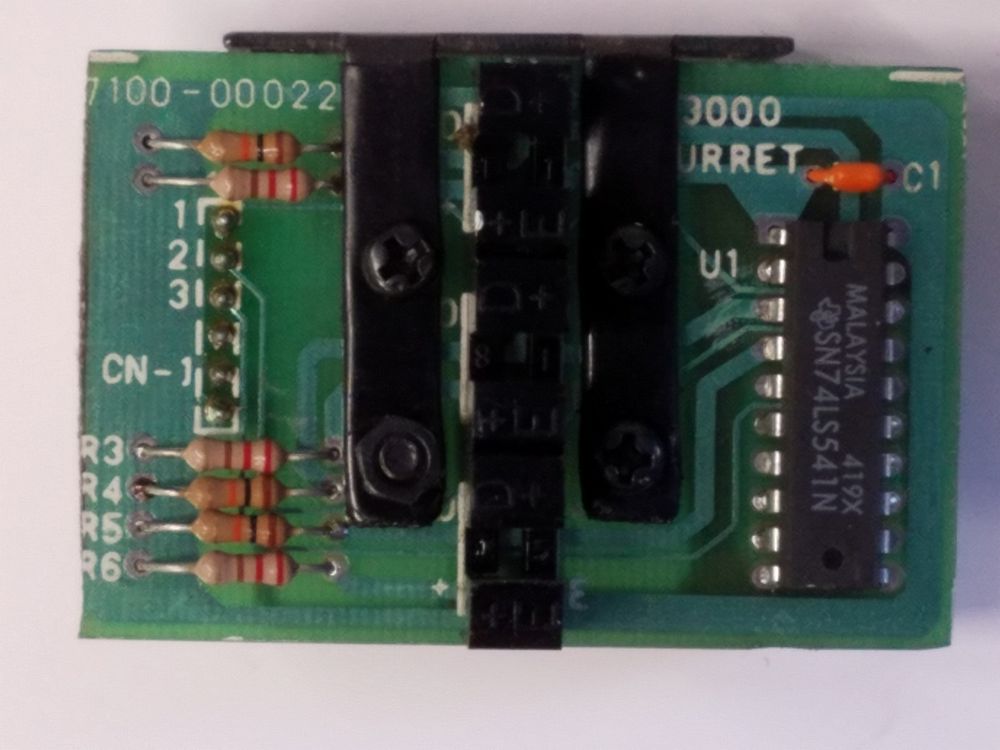
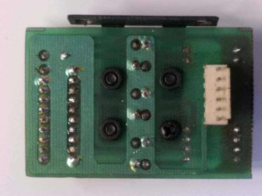
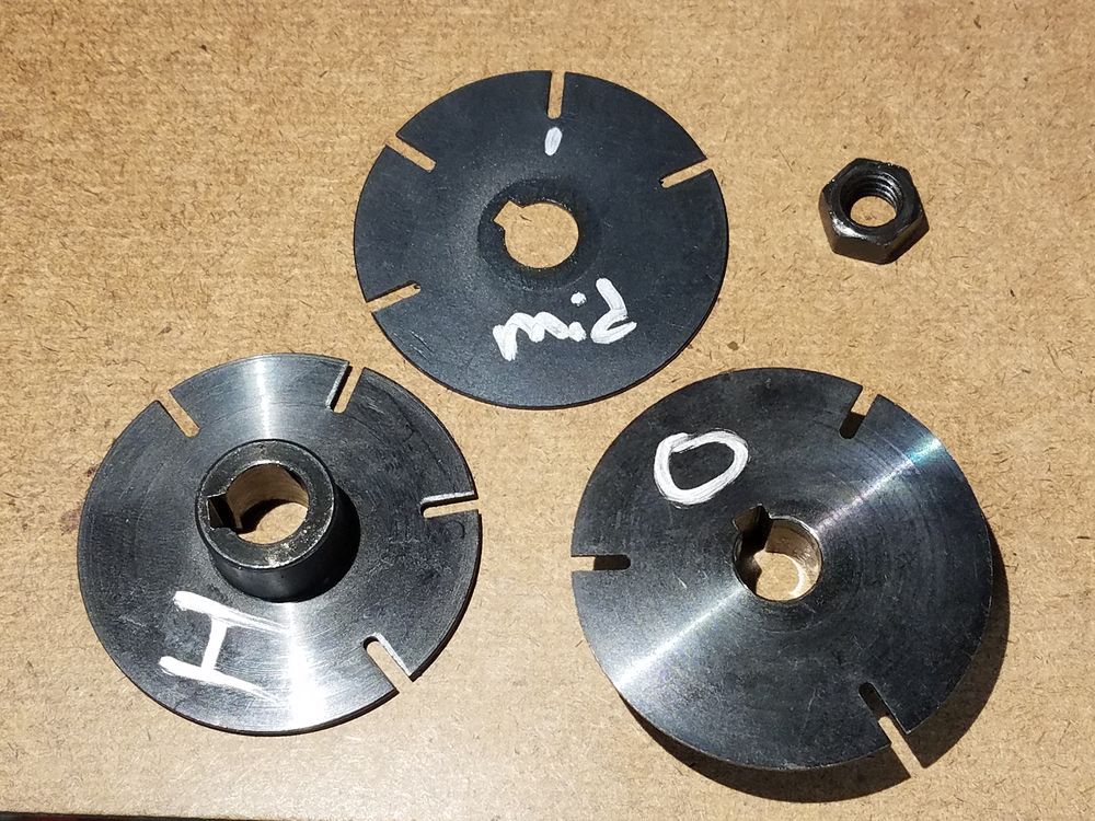
Here is a shot of the original optical sensor setup, there are three optical shutter slots.
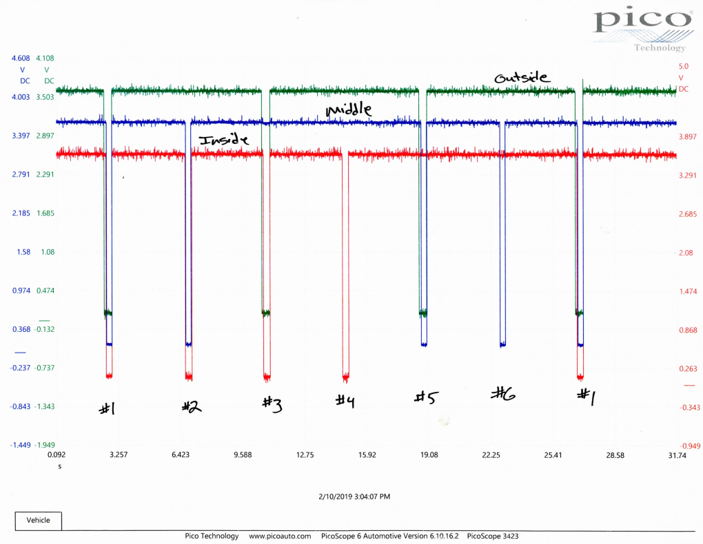
First order of business was to dig out the lab scope and see what was happening when the turret revolved. The sensor in the turret is a TTL Optical setup, 3 bit output. Signal pulls low when the shutter wheel passes through the sensor. The timing of the slots was problematic, the Acorn controller was too fast and mis-interpreted the #1, 3 & 5 positions, mostly position #1. Changing the timing of the outside shutter was problematic and I abandoned the three sensor setup.
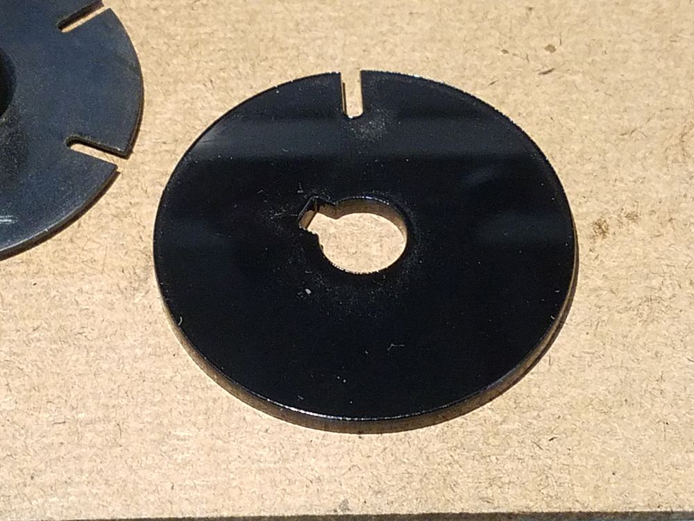
I laser cut a new shutter wheel with only one slot (tool #1) to accommodate the Acorn Timed Turret system. A mounting bracket and plate was then fabricated. Once again the laser came into play in the manufacture of the sensor mounting plate. All plastic parts are cut from 1/8" acrylic sheet.
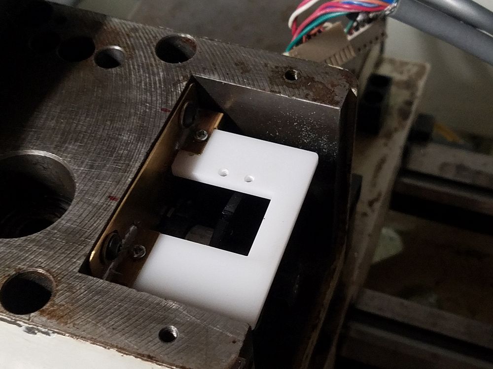
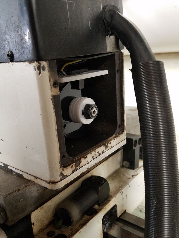
Installed sensor board with Omron EE SX674A optical sensor installed
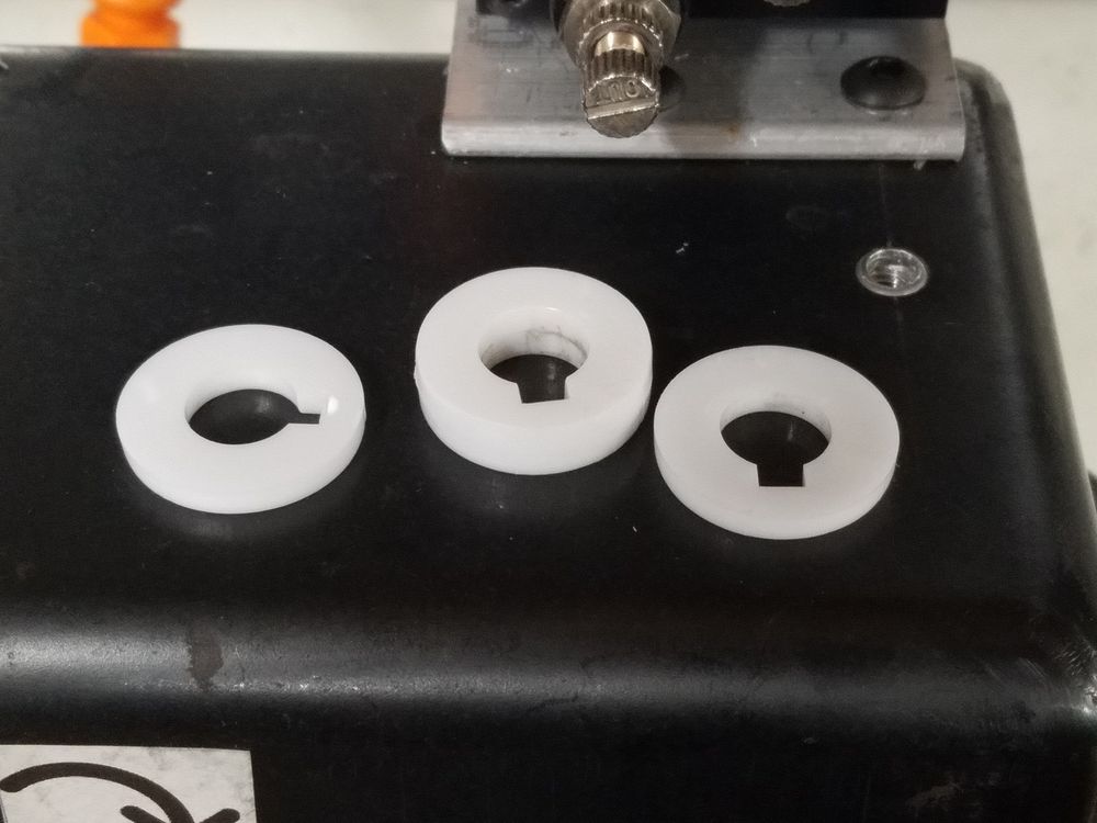
The laser was used to cut a stack of spacers to replace the original shutter wheel.
Turret drive is next...
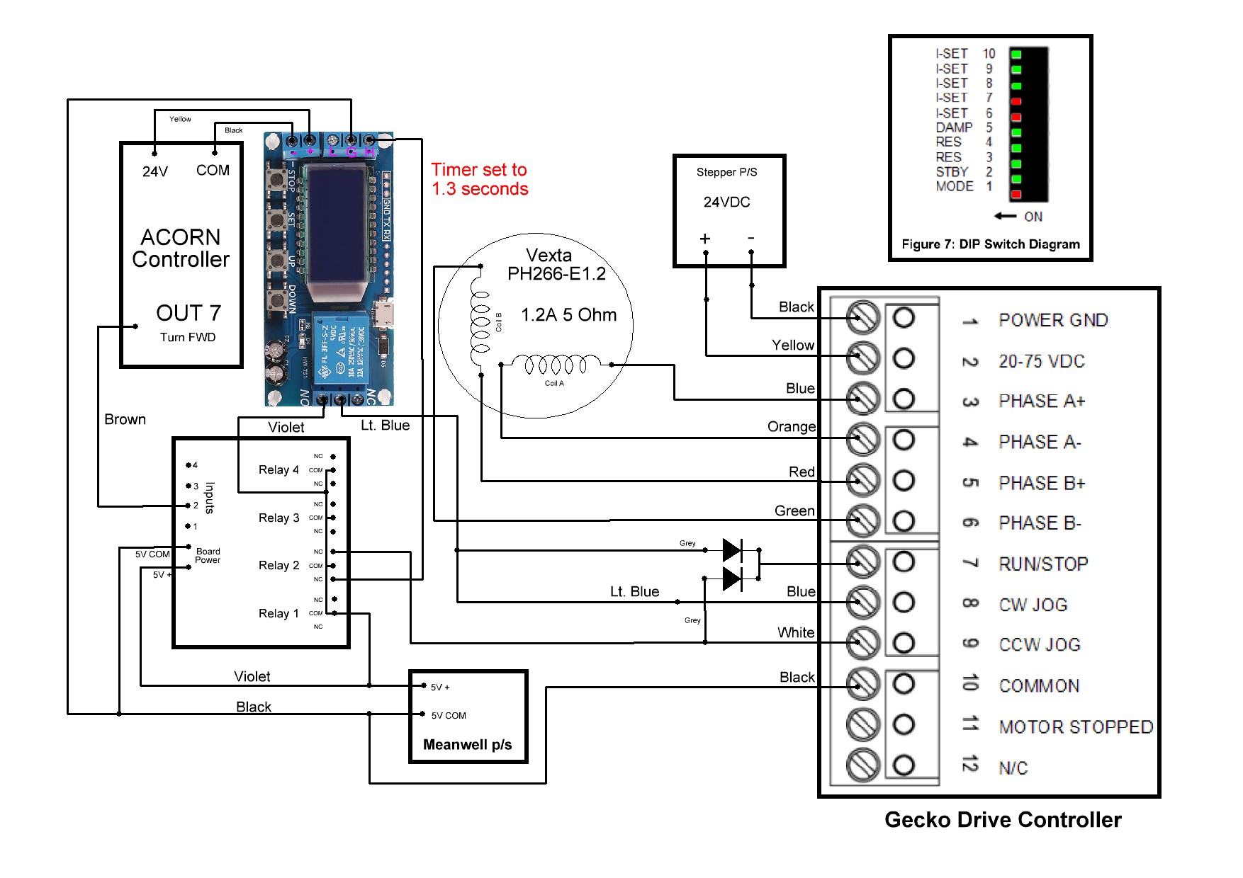
The Gecko G216 Stepper Driver module diagram. This driver can be set to make the stepper act like a motor. Spin of the motor is controlled by an output pins on the Acorn instead of Step/Direction pins. By setting the mode type to VCO mode, the Step and Direction pins will then act as a Forward or Reverse input. There are two potentiometers on the driver that allow the speed of the motor to be set, each direction independently if desired. DIP switch settings are documented in the drawing along with the isolation relay module.
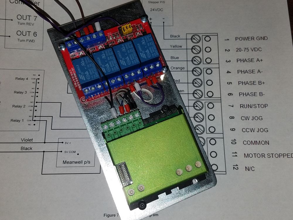
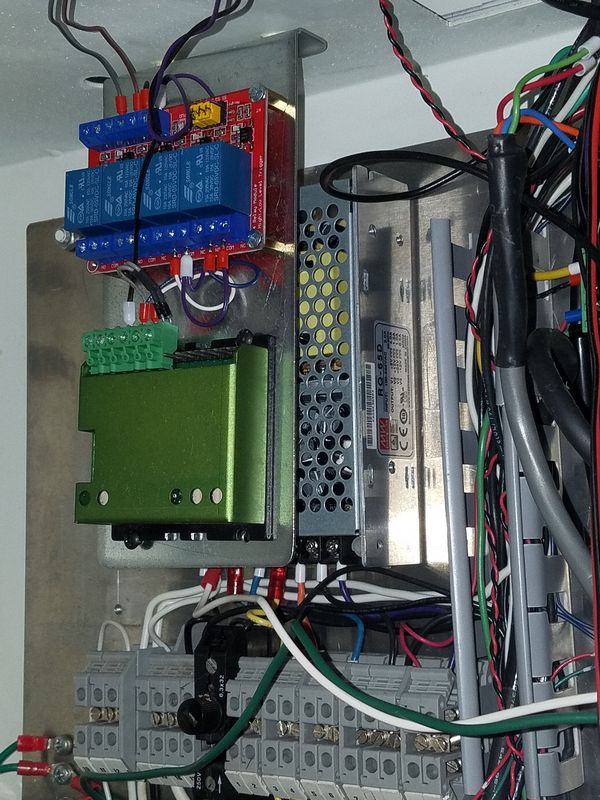
A bracket was fabricated to hold the Gecko drive and the required relay board. This assembly bolts to the ceiling of the cabinet as I have run out of "wall space". After a final check of the wiring I put the controller into diagnostic mode and monitored the inputs as the turret revolved. Ultimately in the end, only one relay was required but I elected to not change out the board.
I have a video here showing the diagnostic mode from the point where I was planning on using a three rotor encoder setup: https://www.youtube.com/watch?v=kHPMAhqw3sQ
The Acorn Timed Turret system uses only one optical sensor to set the sync pulse for tool #1. Subsequent tools are located by turning the turret a prescribed amount of time. There is no positional information for anything other than toll #1. The mechanical design of the turret required that the turret be backed up against the hard stop. As the turret is rotated in the forward direction, the hard stop is spring loaded and lifts when the turret passes a tool position. Once past the position the turret is backed up until it is locked on the hard stop ensuring precise positioning of the tool.
The Acorn controller will first need to be synced to tool position #1. This only needs to occur when the system is started up and not again as long as the system is kept running. In case of an E-Stop event the position is retained. However a missed tool position where it stops anywhere in between tools will require a re-initialization. For other tools, the controller runs the turret forward for a predetermined amount of time. Due to the design of the turret mechanicals the turret then needs to back up against the stop.
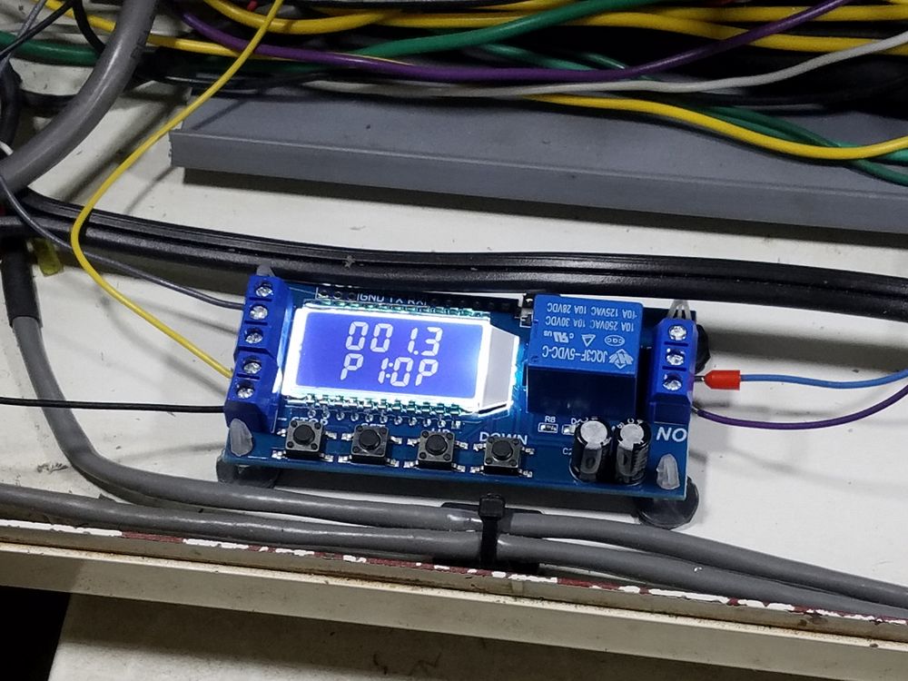
To accomplish this, a time delay relay board is added to briefly back the turret up until it hits the hard stop once the controller stops the forward movement. The relay is driven by the normally closed contact of the turret motor relay. Acorn turns on the turret motor relay by closing the NO contacts and the motor turns in the CW direction until the controller turns off. The amount of time the relay is energized is based on how much time the controller decides the turret needs to rotate. This is about 2 seconds per tool position. When the relay de-energizes, CW rotation stops (actually a little past the hard stop location) and the NC contacts close and this turns on the time delay relay, reversing the rotation. The turret rotates CCW for 1.3 seconds to back up on the hard stop..
Next step, Software!
As mentioned above I am using the Timed Turret system in the Acorn controller. The setup and programming instructions are linked here. Setup is pretty straight forward and simple. The additional software components need to be loaded into the Centroid Lathe directory on the machine's PC. Version 4.50 or later is required to accommodate the turret controls. Looking at the document you will need to set up the following settings (which can change at any time in the future):
Parameter #6: 1 (turns on ATC)
Parameter #160: 1
Parameter #161: 6 (the number of positions on my tool changer)
Parameter #830 5 (type of Automatic Tool Changer)
Parameter #975 2050 (the time in milliseconds that it takes to move one tool position)
Acorn Input IN4 (ToolTurretSyncBit, the sensor pulse for tool #1)
Acorn Output Out 7 (RotateToolTurret, the output control tot eh Gecko Stepper Controller)
Once these are set, tuning was required to get the correct balance between the time in forward motion and reverse motion to get accurate positioning of the turret. A little bit of stepper buzz when reversing to the stop needs to be tolerated due to slight differences in movement of the turret. If I were to go back into the turret and move the sensor location I could likely get this reduced quite a bit or even eliminated. Given the amount of time I have into the project, this will have to be delayed until my ambition returns. The turret positions just fine as set.
Turret drive video can be found here...