Spindle Encoder
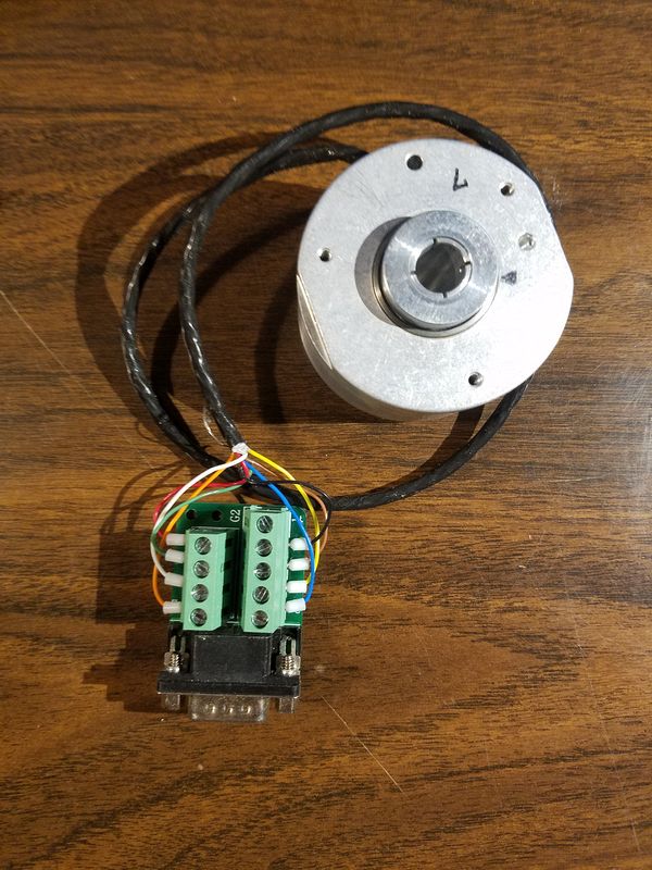
The Acorn will support a spindle encoder which will allow for Rigid Tapping. I had a couple of encoders rattling around and decided to upgrade to a spindle encoder.
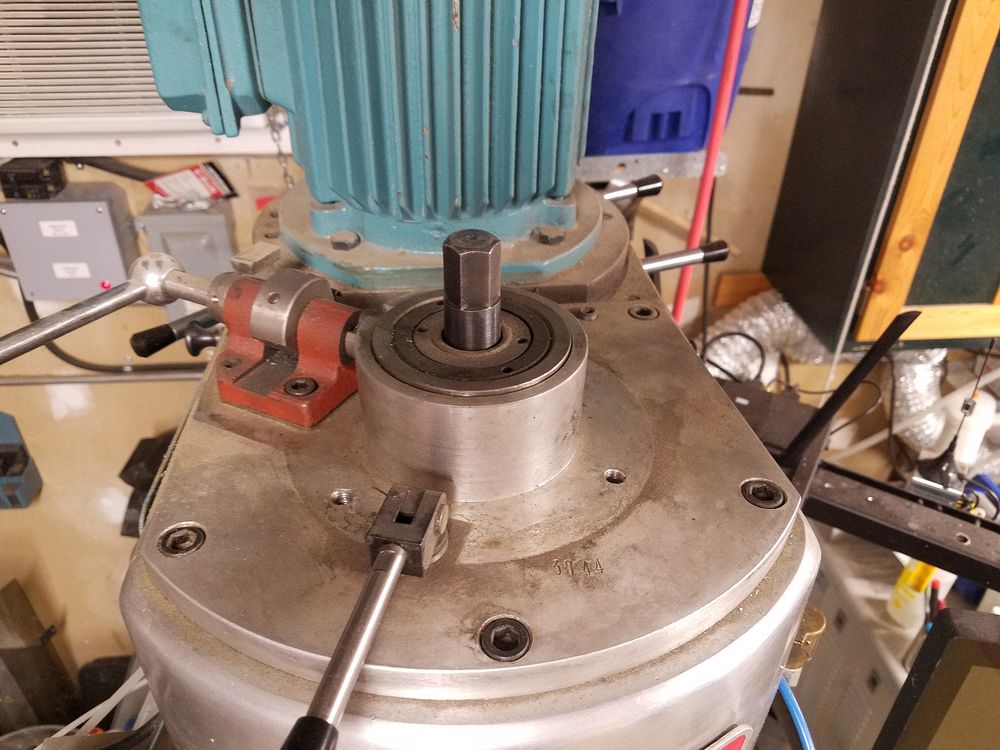
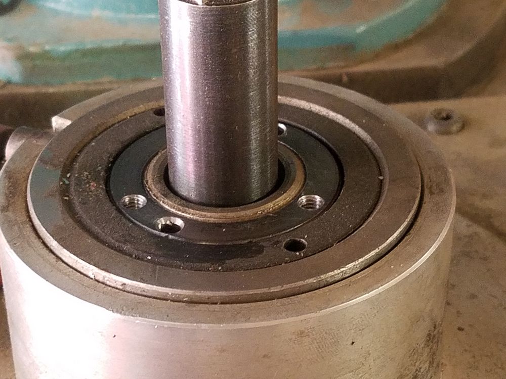
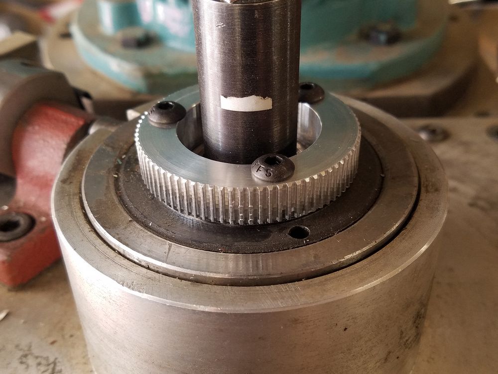
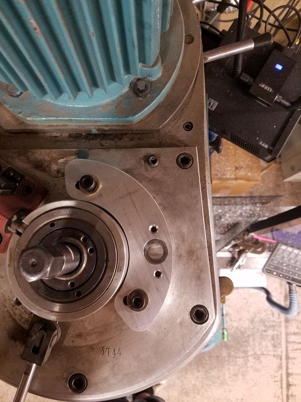
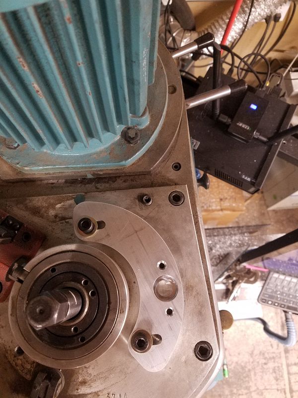
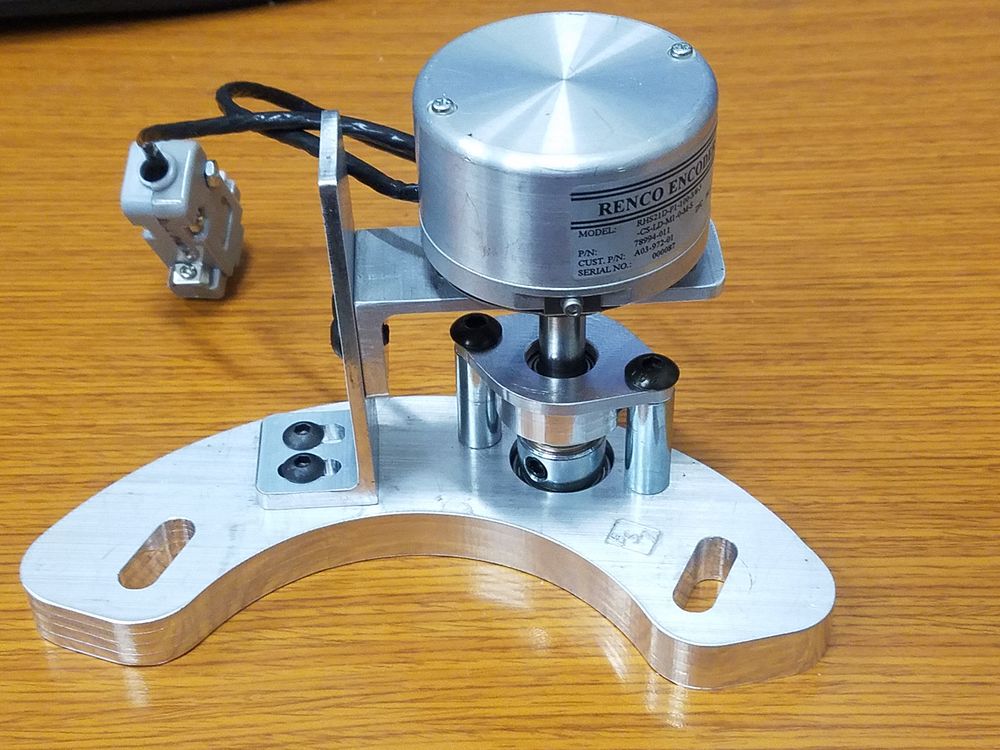
I installed a DE9 breakout to test the encoder. It worked! Here is what I have to work with after removing the upper cover. Nice flat area to mount the parts with pre-drilled mounting bolt holes.
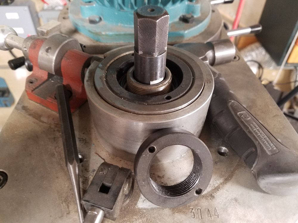
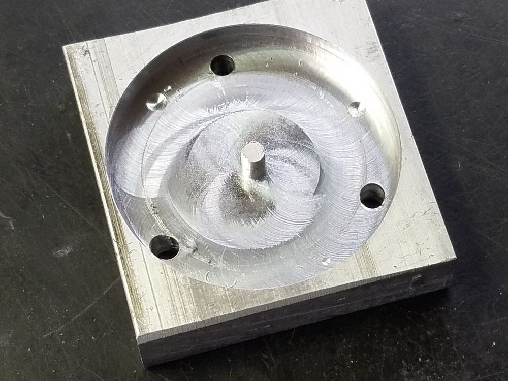
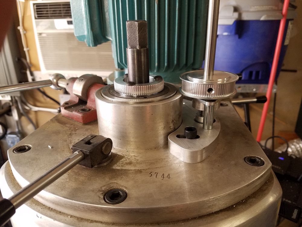
I removed the locking ring. The locking ring, the shaft it threads onto and the draw bar are the only moving parts up here. Plans are to bolt a timing pulley to this ring. I drew up and machined a drilling jig to accurately mark, drill and then thread holes for the 10-32 mounting screws.
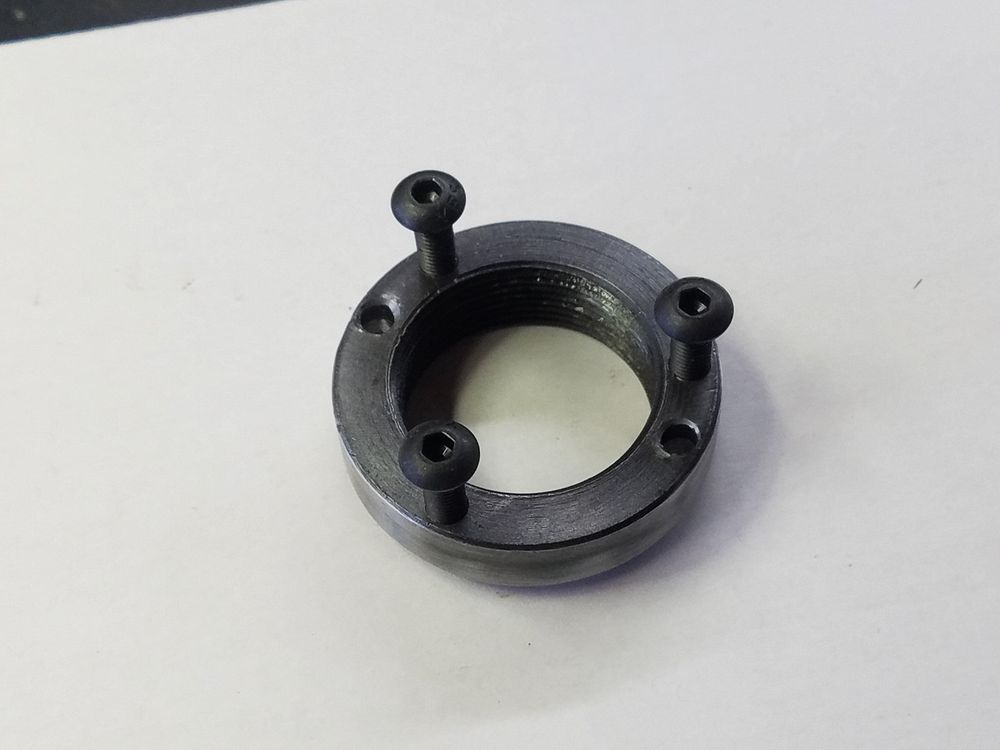
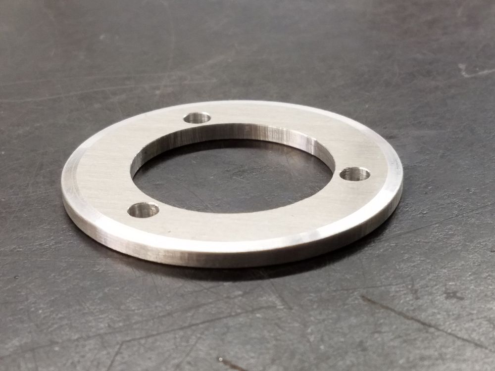
Lock ring with pulley mounting holes drilled and tapped. Right side show ring re-installed
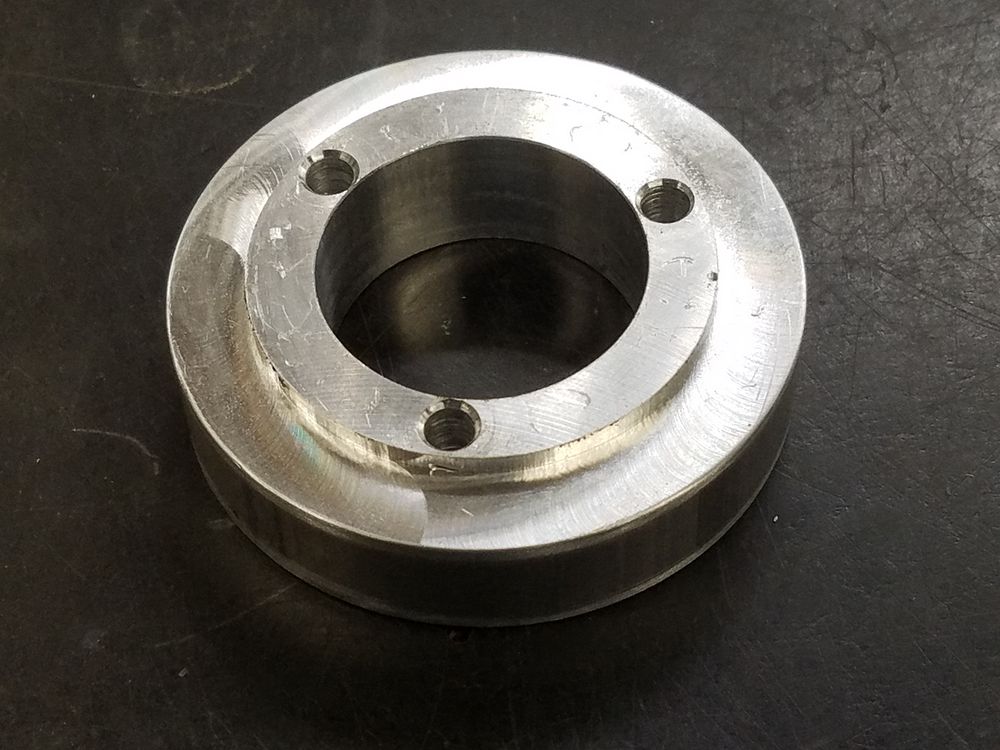
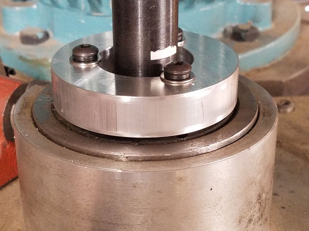
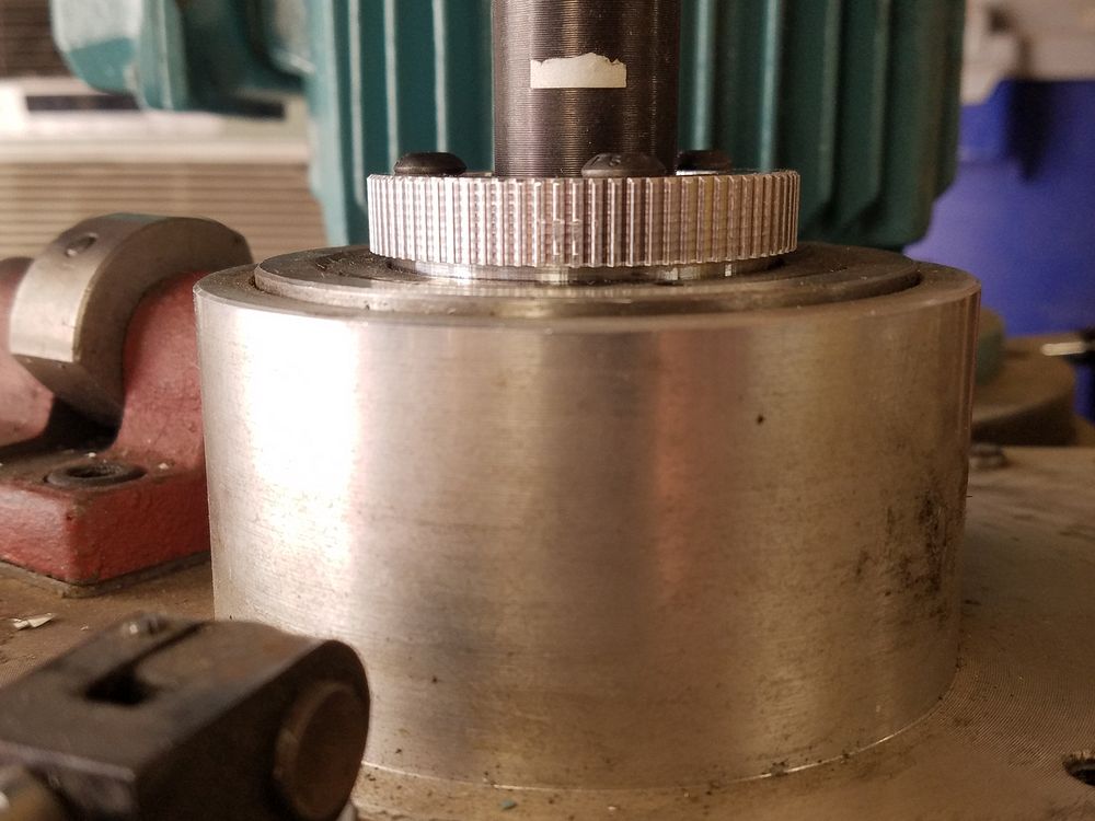
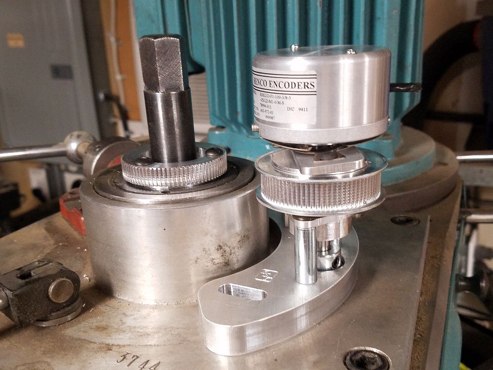
I used a piece of AL round stock and turned a test "pulley" to verify clearances and fit. The raised portion is required to have the pulley clear the outer fixed lock ring. Right side shows the "pulley" installed.
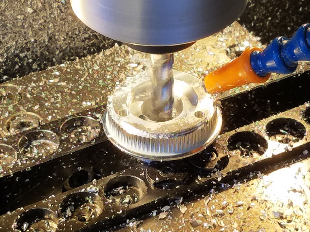
Using the Mitee Bite Versa Grip vice jaws I grabbed the hub of the pulley and proceeded to drill the mounting holes, create the stepped face and bore the middle. The pulley was then mounted in the lathe to remove the hub and remaining flange.
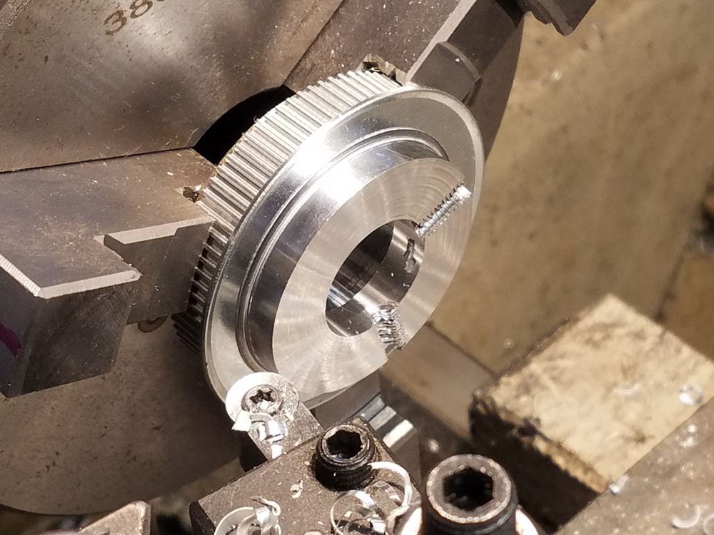
The finished spindle pulley. Spindle pulley installed, showing the step to allow for clearance as the lock ring sat a little below the rest of the parts. The step is 0.080" and really could have been 0.030", but I wanted to leave enough room to sneak an indicator tip in, just on the off chance I needed to tweak the centering of the pulley. It ran true on the first try...
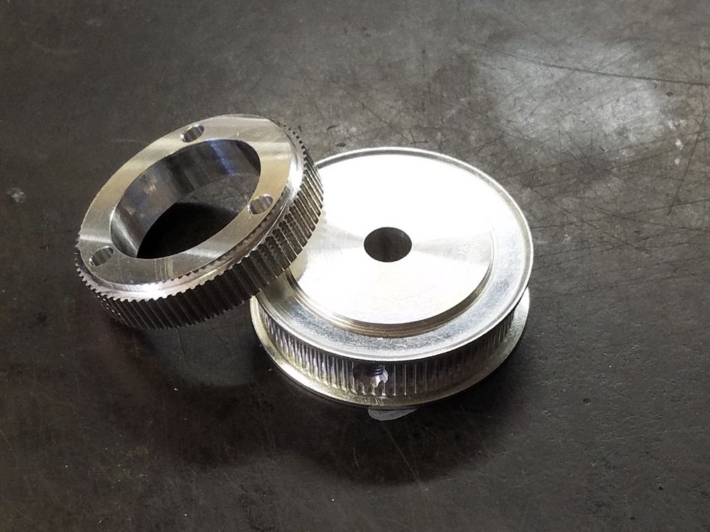
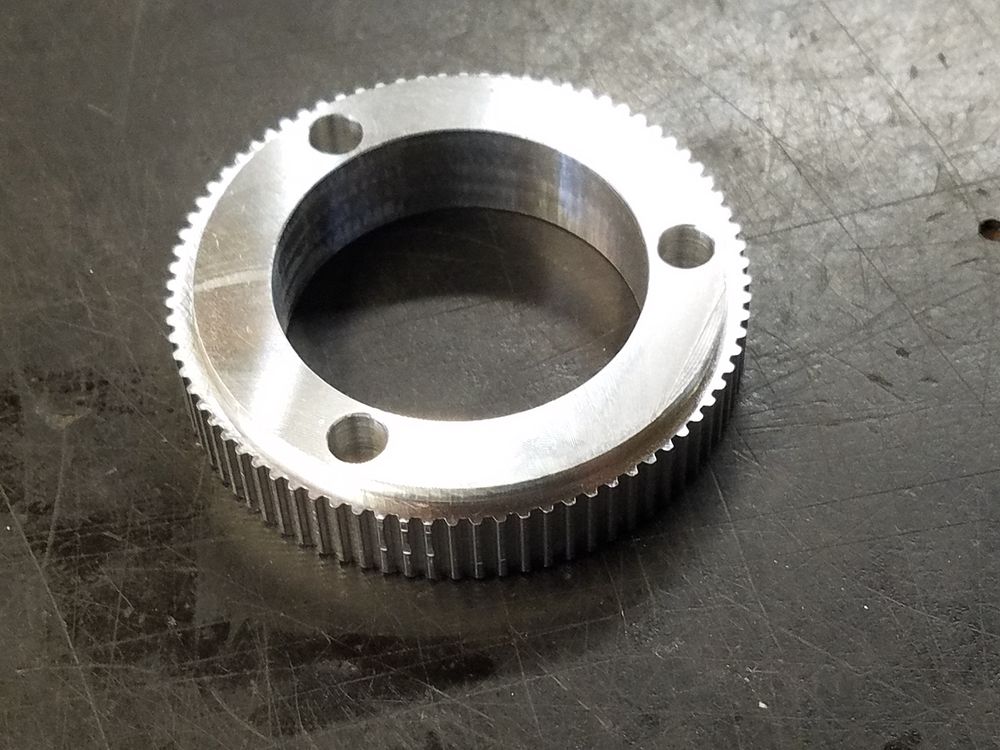
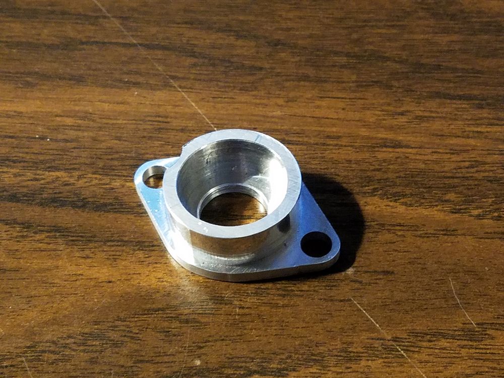
Additional view of spindle pulley showing the ID that allows for access to the spindle drawbar. The finished Encoder pulley. The only real modifications needed were to bore and ream the hole to 0.375" to match the jack shaft, remove the 0.500" tall hub and relocate the setscrews. Now I have a finished set of pulleys.
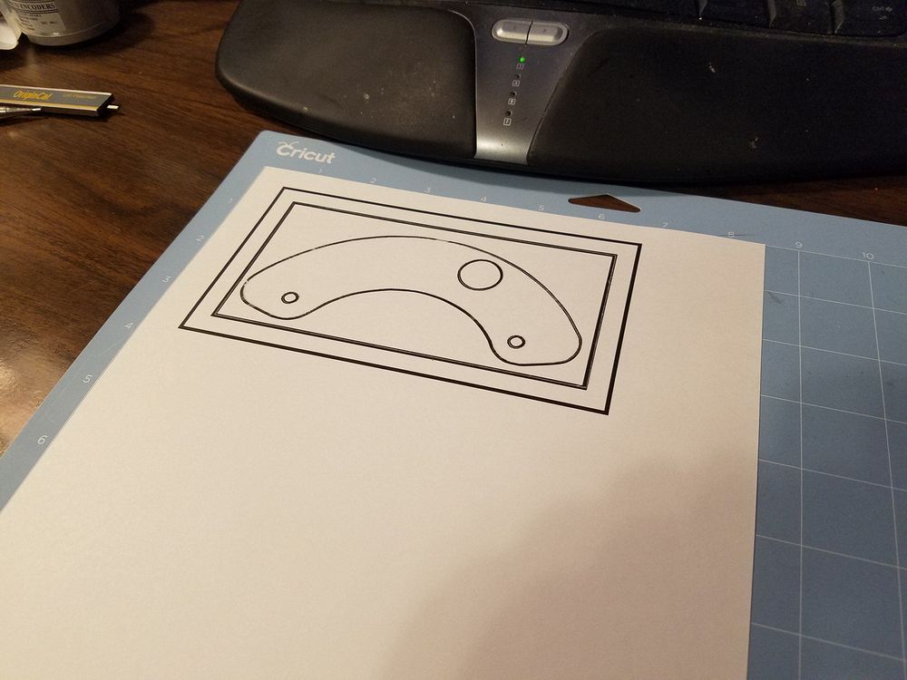
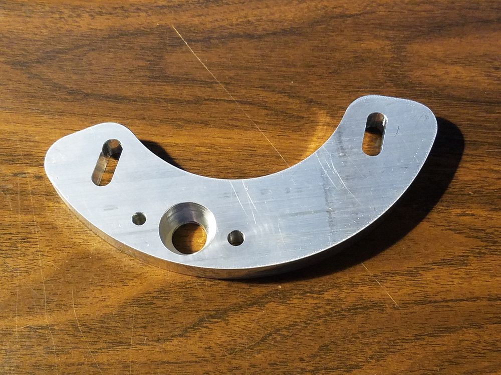
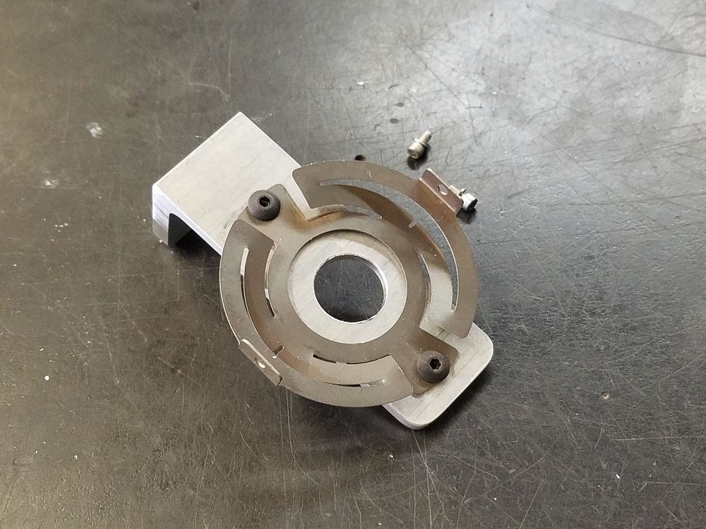
Next to fabricate was the main mounting bracket. I need to provide a place to mount the planned jackshaft. I recently purchased a Cricut Maker crafting machine and discovered I can impart the DXF's from Turbo CAD and cut cardstock pieces for testing. I used to use the 3D printer to print a thin sample, however this is much quicker A 7/8" OD 3/8" ID bearing will be pressed into the pocket of the 1/2" thick plate. The two holes on either side of the bearing pocket will be the mounting point for the upper bearing housing. The shaft will be 3/8 hard rod.
The slots allow for about 1/4" of travel for belt adjustment. Left and Right most positions shown.
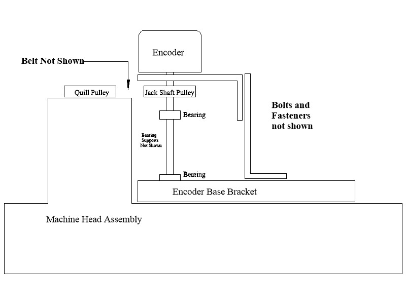
Here is a sketch of how I plan to stabilize the encoder body. The encoder input shaft will be fastened on the top end of the jackshaft. Slotting of the two support brackets will allow full adjustment of the assembly.
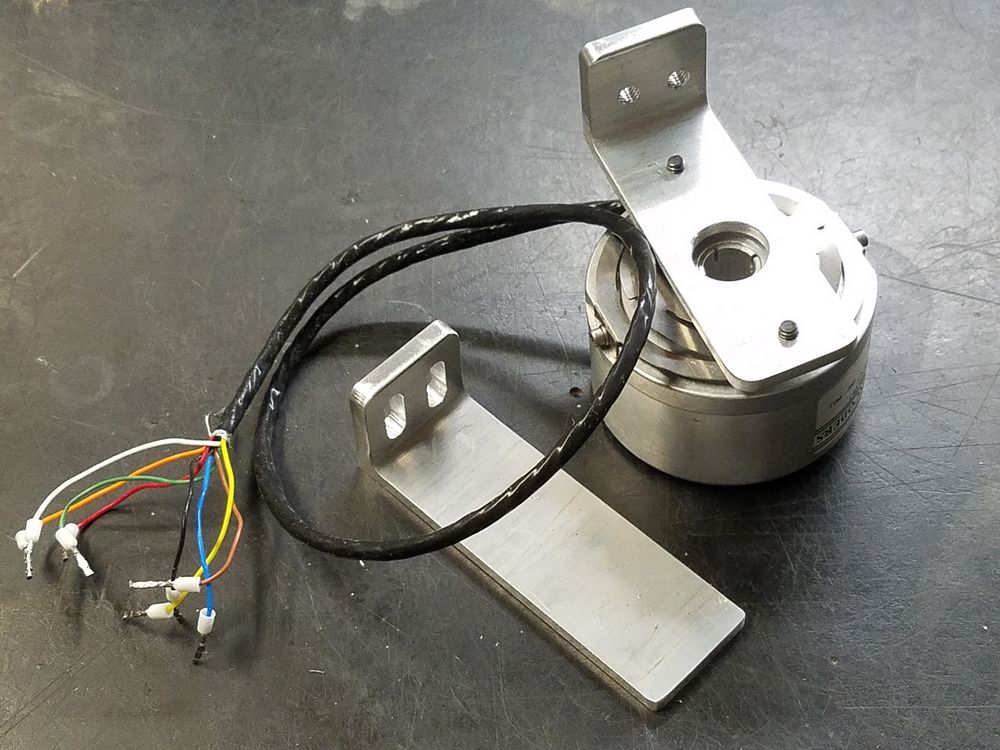
An "L" bracket was made to support the encoder body. Here is the supplied spring mount on the "L" bracket. On the right we have the Encoder mounted on the upper half of the bracket via the spring mounting with the lower half of the bracket next to it. Final slots for the bolts will be machined in the upright bracket once the shaft and pulleys are in place.
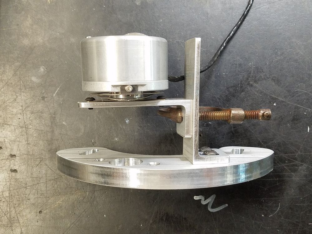
Everything except the height adjustment slots could be machined without completion of the jack shaft mounting. A C-clamp provided a temporary test fit. Placement test of the assembly.
The jack shaft's upper bearing mounting. The bearing will be pressed into the cup. The upper bearing mount was machined from 1/2" aluminum plate. Spacers were used to support this in relation to the shaft and lower bearing. Right image shows the jack shaft and encoder minus the pulley. This shows the overall layout of the design.
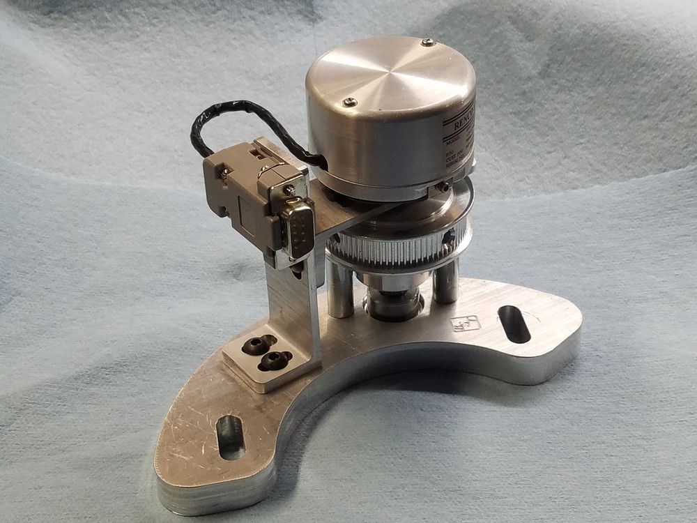
The pulley alignment was checked using the partially competed jack shaft assembly. The shaft was cut to length, flats machined for the setscrews to grip and then assembled. I will need to remove the encoder to install the timing belt when it shows up later in the week. I have a total inability to accurately calculate timing belts, so there are three in total on the way. The encoder cord was shortened and a DE9 was mounted to the upright. Later on, I discovered that the data cord would pass close enough to the spindle draw bar as positioned. This would make access to the draw bar for the infrequent tooling change a threat to the life of the encoder. A subsequent bracket was made to relocate the DE9 connector
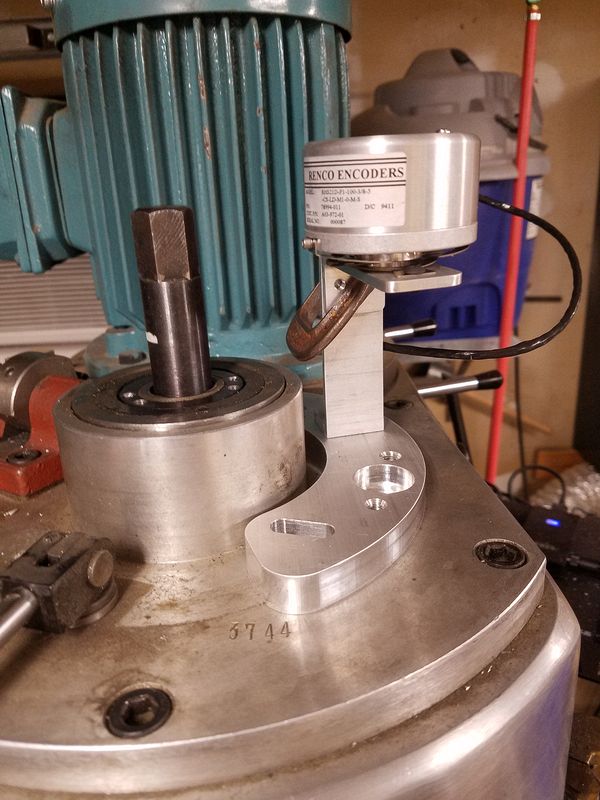
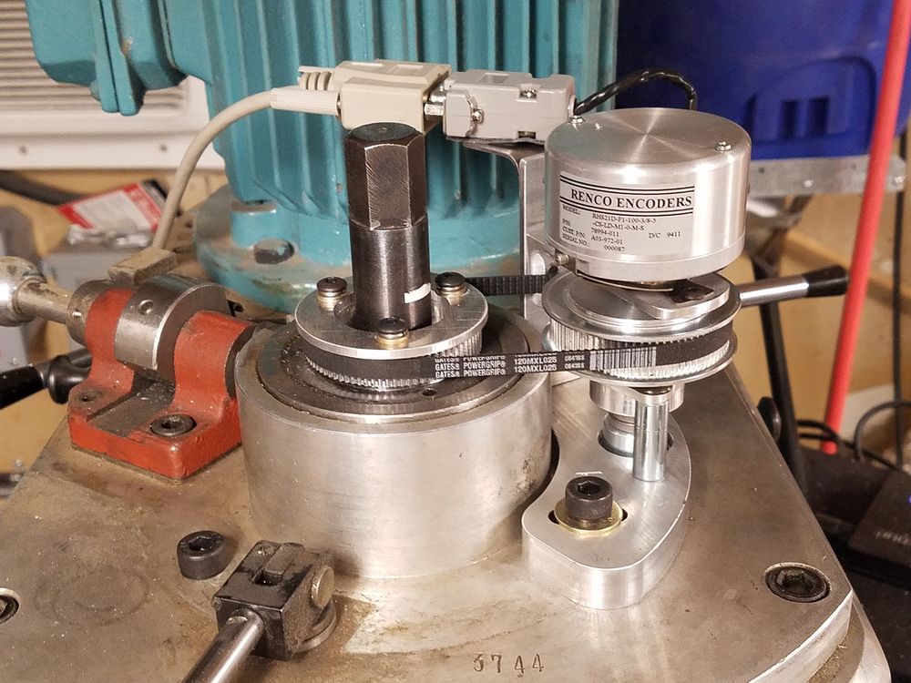
Encoder assembly in place for belt measuring and alignment. Belt length was calculated at 150 tooth, I ordered a 145, 150 and 155 tooth to hedge my bets. For the first time ever, my calculation was correct! Go figure... Next step was to make a new flange for the pulley as the mounting bolts would have distorted the original pressed on flange. I used the same CAD drawing to make the flange, just increasing the OD. After it was machined I mounted it in the lathe and cut a bevel.
5/30/2021 Finished Encoder Installation
Note the repositioned DE9 connector and bracket. You can also see where I had to bevel the encoder bracket. At higher speeds the belt started to rub on the bracket. Other than these two issues, the assembly wound up being built as designed.